Monday 6 July 2015

The Frame

A Few Repairs

Fortunately, using the Rupert Ratio frame checking method, the frame proved to be straight. However, a few minor repairs were still necessary.

The bike is a single seater and should not have rear foot rests. In a previous post I showed how some foot rests had been crudely welded on to the swing arm. These were cut off and the remaining weld was carefully ground away.
Non Standard Fitments.


The swing arm repair can be seen here.

The frame itself had a broken weld where the rear brake pedal bush had come away from the frame. This manifested itself in a sloppy rear brake pedal. A quick trip to a local metal fabrication specialist had it better than new.

A Simple Frame Stand


Before starting the frame preparation (see below) I decided that the frame should be supported in some way. I decided to construct a simple frame stand using a Black & Decker Workmate. This involved fabricating two alloy brackets and bolting them to the Workmate using the predrilled holes. By positioning the brackets in line with the foot peg studs on the frame the Workmate can be adjusted to secure the frame firmly with the alloy preventing any thread damage.
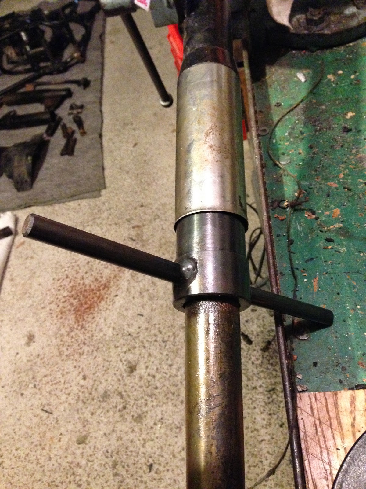
Makeshift Clamp

Alloy Brackets Attached to the Workmate

Painting

With the frame repaired it was time to start the preparation for painting. I decided that I would do this by hand rather than sand blasting as the frame was in reasonably good condition. It has always been my intention to spray the cycle parts with a cellulose paint rather than applying a powder coat finish.

Manually preparing the frame turned out to be very challenging indeed an soaked up many hours of effort. However, the results have been worth it and a few pounds have been saved along the way.

It was interesting to see just how simple the original paint finish was, it appeared to be a single coat of black painted directly onto the bare metal. Its hard to criticise this though as 49 years later it is still in fairly good condition.

Start of the Preparation

The frame was prepared in stages and at each stage the prepared area was immediately spayed with a metal primer.

A Coat of Primer to Protect the Frame
Once the frame preparation is complete, the primer will be rubbed back and recoated before applying the topcoat and lacquer.


Once the frame is complete, the remaining cycle parts will be tackled.


Saturday 14 February 2015

Front Forks

After my ordeal with the rear suspension, I started the task of stripping and inspecting the front forks. The forks had already been removed from the bike during the initial teardown. However, it was time to take things a little further.

The first task was to remove the chrome oil seal holders. For this a special tool is required. I have heard of people using all manner of implements to try and perform this task, however, these were extremely tight and I would recommend purchasing the special wrench.


Once the oil seal holders are off, it is a simple job to remove the stanchions and get to the bushes.


 A few cir-clips later and the whole front suspension is ready for cleaning and new bushes.

Ready for Cleaning
New Bushes and Ball Bearings


Swing Arm Bushes

You may remember from my last post that I was left feeling disappointed that the swing arm bearings would not come out. It seems that this is a common problem and that expert advice suggested that some ingenuity was required.


I was to be replacing the bearings and the swing arm pivot pin which gave me plenty of scope in terms of the old one. So the first thing I did was cut through the pin on each side of the swing arm with a suitably curved hacksaw blade and transfer the arm to the bench.


Once on the bench all attempts to remove the pin and bearing by the usual methods of pushing, pulling, swearing etc failed. It is particularly tricky challenge as the bearing is effectively fitted to a blind tube and can only really be pulled out. In my case the bearing had bonded itself to the swing arm.

By passing a hacksaw through the hollow pin, I was able to cut through the wall of the pin and the inner sleeve of the bearing. This allowed, with much effort, the pin and sleeve to collapse and be separated from the rubber section. Eventually all of the silent block rubber could be cut away leaving the thin outer sleeve firmly attached to the swing arm.

Although not obvious, protective jaws were
used to grip the swing arm.
The outer sleeve had to be removed with a cold chisel. 


Here it is several hours later, removed.